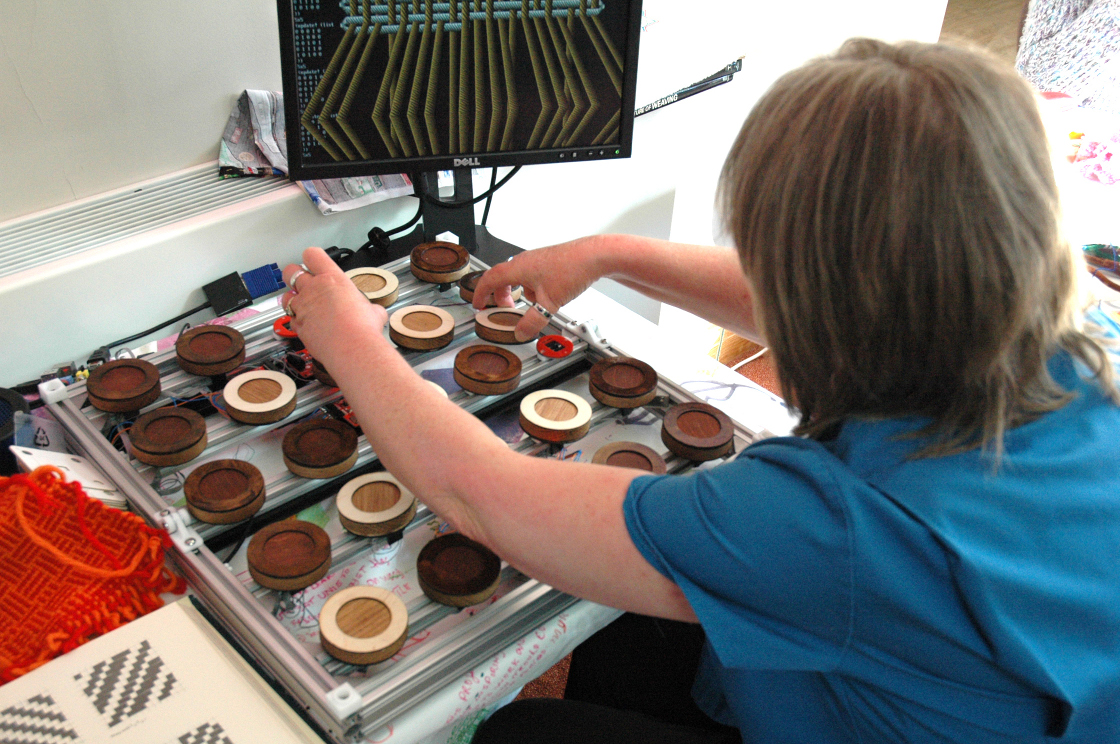
Here is a member of staff at Miners Court trying some tangible weave coding in the midst of our crafts area – at the moment it’s simply displaying the weave structure on the simulated warp weighed loom with a single colour each for warp and weft threads, the next thing is to get ‘colour & weave’ patterns working.
The pattern matrix is the second generation of tangible programming device from the weavecoding project. It’s been built as an open hardware project in collaboration with Falmouth University’s Makernow fablab, who have designed and built the chassis using many 3D printed parts and assembled the electronics using surface mount components (far beyond my stripboard skills).
Here you can see the aluminium framework supporting the AVR based row controller boards with the Raspberry Pi in the corner. The hall effect sensors detect magnetic fields – this picture was taken before any of the wiring was started.
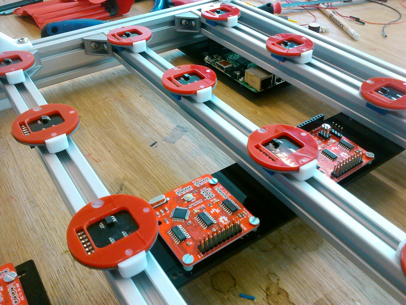
The row controllers are designed to read the sensor data and dispatch it to the Raspberry Pi using i2c serial communication running on their atmega328 processors. This design was arrived at after the experience of building flotsam which centralised all of the logic in the Raspberry Pi, resulting in lots of wiring required to collect the 128 bits of information and pass it to the GPIO port on the Pi. Using i2c has the advantage that you only need two wires to communicate everything, processing can be distributed and it can be far more modular and extendible in future. In fact we plan to try different sensors and configurations – so this is a great platform for experimenting with tangible programming.
This video shows the current operation of the sensors and row controllers, I’ve programmed the board with test code that displays the state of the magnetic field with the status LED, making sure that it can tell the orientation of the programming block:
The row controllers have a set of multiplexers that allow you to choose between 20 sensor inputs all routed to an analogue pin on the AVR. We’re just using digital here, but it means we can try totally different combinations of sensors without changing the rest of the hardware.
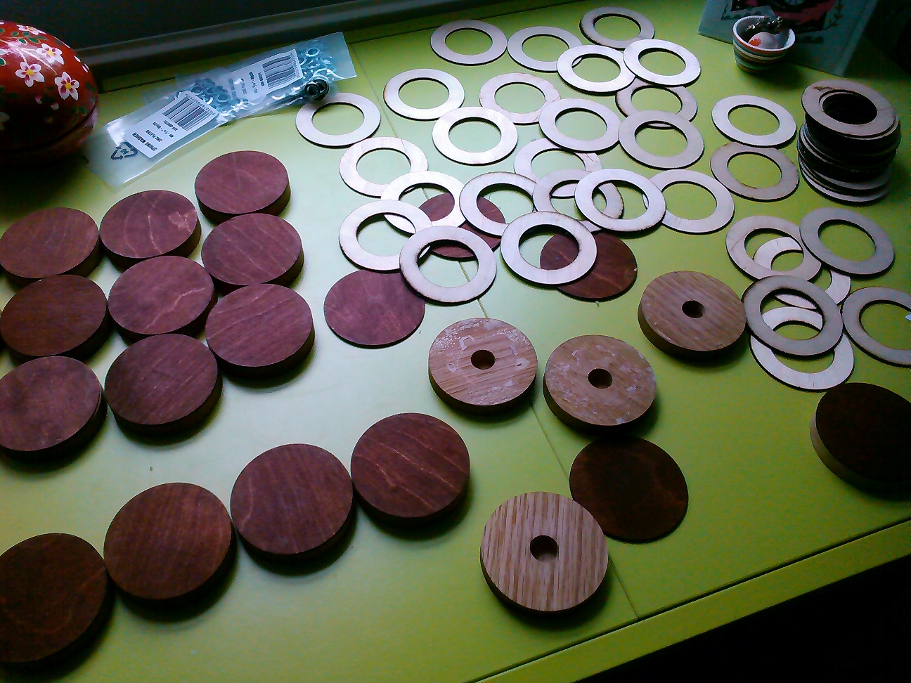
After getting the first couple of rows working and testing it with elderly people at our Miners Court residency there were a couple of issues. Firstly the magnets were really strong, and I worried about leaving it unattended with the programming blocks snapping together so violently (as we plan to use it in museum settings as well as at Miners Court). The other problem was that even with strong magnets, the placement of the blocks needed to be very precise. This is probably to do with the shape of the magnets, and the fact that the fields bend around them and reverse quite short distances from their edges.
To fix these bugs it was a fairly simple matter to take the blocks apart, remove 2 of the 3 magnets and add some rings to guide placement over the sensors properly:
3 thoughts on “Pattern matrix – putting it together”